The front panel lit up
As I mentioned, most of the parts I already had lying around. This is a (hopefully) complete parts list:
- 1 * AVR Atmega168
- 1 * 32.768 kHz crsytal (salvaged from something with a clock function)
- 2 * Thumbsticks (salvaged from a cheap PC gamepad)
- 12 * 3mm Blue LEDs
- 4 * 5mm Blue LEDs
- 2 * White LEDs (used for screen backlight)
- 1 * 16*2 LCD Display (got a whole box of these for free)
- 4 * Plastic things... I think they were meant to be caps for push buttons, had them lying around.
- 12 * Momentary push switches. They have 3 pins, NO, NC and Common. (Parts box)
- 8 * White knobs for pushbuttons (Parts box)
- 5 * Black knobs for pushbuttons (Parts box)
- 1 * Green and 1 * Red knobs for pushbuttons (Parts box)
- 1 * 74154 1-to-16 decoder, for the lights. (Parts box)
- 1 * 74159 16-to-1 multiplexer, for the switches (Parts box)
- 1 * 74154 8-bit SIPO shift register (Parts box)
- 1 * Light up rocker switch
- 1 * Project box (This was the whole reason for the project, I had this nice box and needed something to put in it!)
- 2 * Stripboard cards (I think they're 'Eurocards'... they're pretty big whatever they are. Stripboard basically) (Parts box)
- Lots of plastic standoff stuff.
- Screws.
- Lots of connectors, headers, wire, solder, drilling, filing, tea.
I think the total cost was somewhere around £15-20, something like that.
Design(top)
 The face design in Qcad
 Everything in place
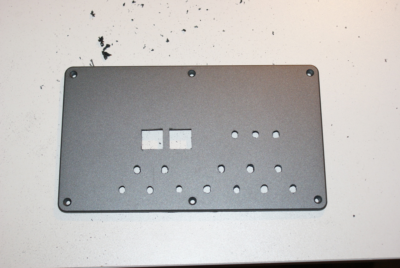
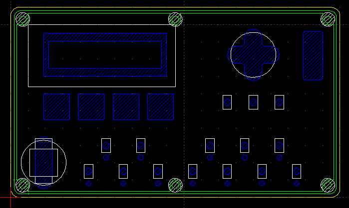
The first thing to do was to draw out the box in QCad and see how I could fit everything in: holes.dxf
Everything in place
The first thing to do was to draw out the box in QCad and see how I could fit everything in: holes.dxf
The blue bits are holes to be cut out, the white bits are the parts inside the box, and the green and yellow bits are the actual structure of the lid of the box. The spacings were done with 0.1" pin pitch in mind, allowing me to use standard stripboard. I don't have the facility to make PCBs.
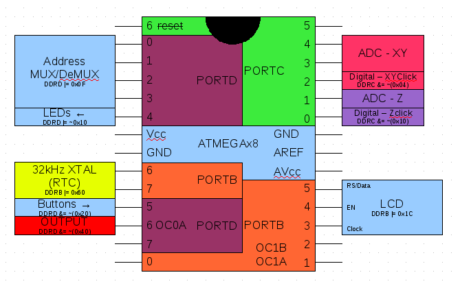
This is the closest I have to a schematic at the moment: block.odd(OpenOffice Drawing)
Seemed like everything was going to be OK - so I set about drilling and cutting with my dremel, then filing to make everything a nice snug fit. It was starting to take shape, none of the parts are fixed down here, just poked into their holes. The stripboard behind was to convince me that my carefully calculated hole spacing would work with 0.1" spaced board.
The face design in QcadEverything in placeThe blue bits are holes to be cut out, the white bits are the parts inside the box, and the green and yellow bits are the actual structure of the lid of the box. The spacings were done with 0.1" pin pitch in mind, allowing me to use standard stripboard. I don't have the facility to make PCBs.
This is the closest I have to a schematic at the moment: block.odd(OpenOffice Drawing)
Seemed like everything was going to be OK - so I set about drilling and cutting with my dremel, then filing to make everything a nice snug fit. It was starting to take shape, none of the parts are fixed down here, just poked into their holes. The stripboard behind was to convince me that my carefully calculated hole spacing would work with 0.1" spaced board.
Electronics(top)
 The board for LEDs, buttons and logic
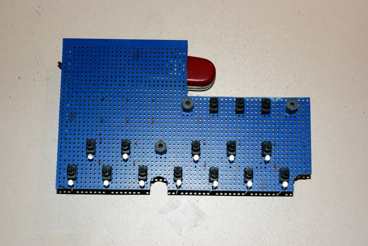
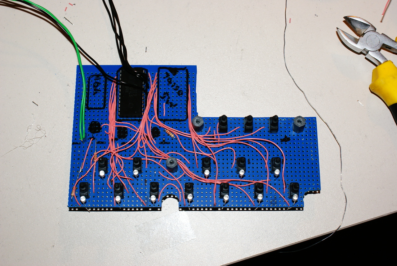
 The beat lights.
I cut the required shape out of some stripboard, and soldered down the LEDs and switches. This will be the board that holds the mux/demux and shift register. They are going in the big space top left.
This part was excruciating, as I had made around a hundred (maybe more) solder joints, and couldn't really test them until it was all done. When I did finish it all, and hooked up the multiplexers to a chip it thankfully worked straight away. I had however connected two of the address lines back to front, an easy fix!
The beat lights.
I cut the required shape out of some stripboard, and soldered down the LEDs and switches. This will be the board that holds the mux/demux and shift register. They are going in the big space top left.
This part was excruciating, as I had made around a hundred (maybe more) solder joints, and couldn't really test them until it was all done. When I did finish it all, and hooked up the multiplexers to a chip it thankfully worked straight away. I had however connected two of the address lines back to front, an easy fix!
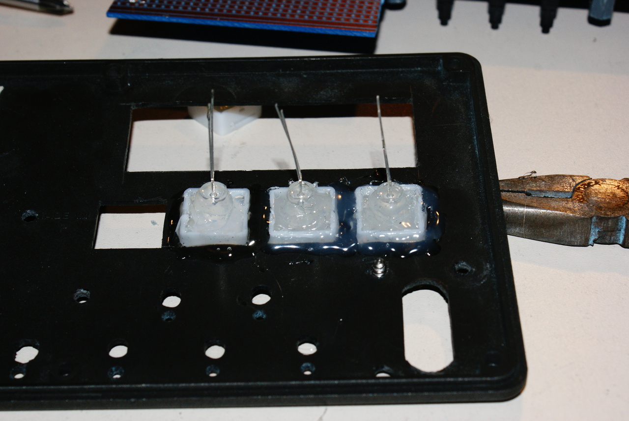
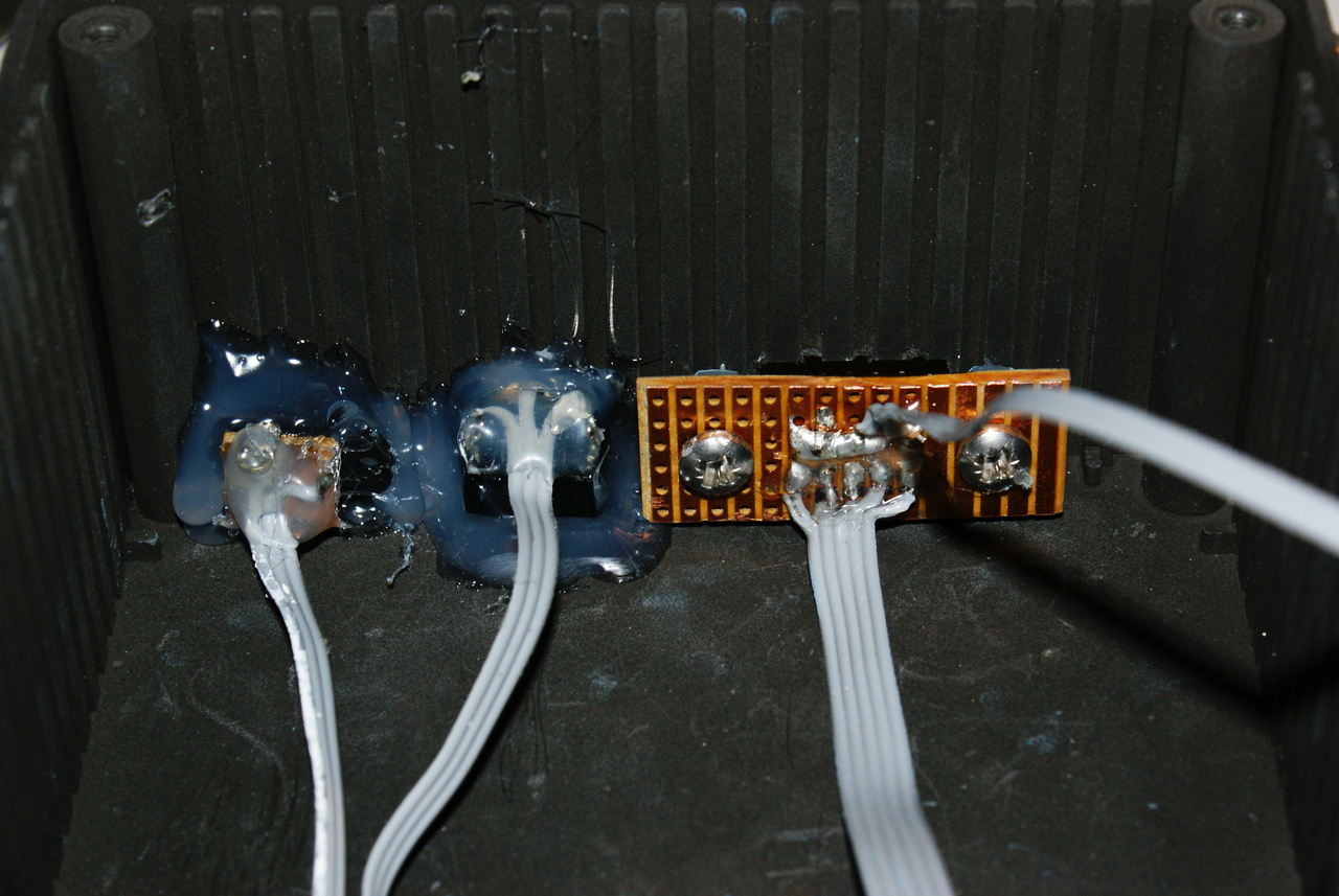
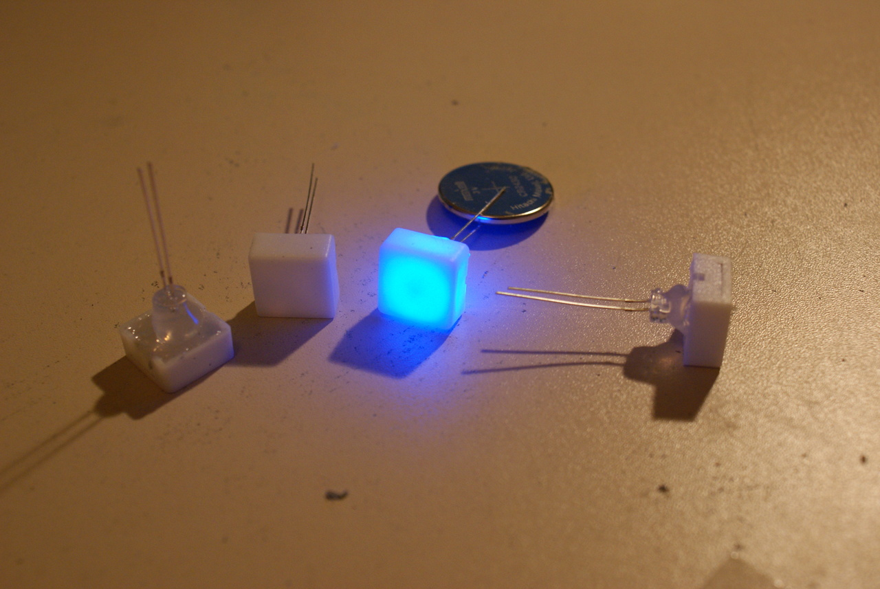
After that, I glued the 5mm LEDs into the 'white plastic thingies' using a glue gun for the beat counter. They turned out really nice I think.
So far so good, next I added a backlight to the LCD by removing the reflective layer from the back, adding a diffuser and wedging some LEDs in the side. Its not the prettiest LCD in the world, but hey, it works for the most part. The pen is to remind me which way round it goes back on the PCB!
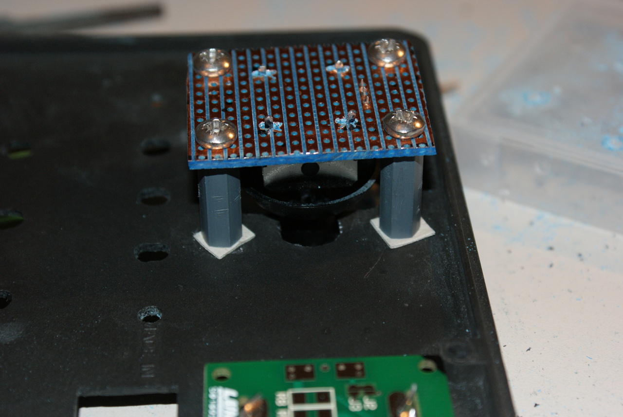
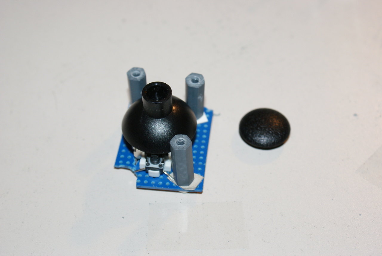
Then I had to mount the thumbsticks, which have a really awkward pin spacing. Nothing a little drilling couldn't fix. Note the cardboard washers at the ends of the standoffs - they were just a smidgen too short and the stick didn't move freely. A millimeter of card did the trick
I had put off permanently mounting anything to the lid for as long as I could, but it came to crunch time, and I started glueing bits in. It's only the beat lights, the LCD and the side panel connectors which are actually glued in. The rest is all screwed to standoffs. A little more wiring, some screwing and drilling and a breadboard later and the front panel lived!
The board for LEDs, buttons and logicThe beat lights.After that, I glued the 5mm LEDs into the 'white plastic thingies' using a glue gun for the beat counter. They turned out really nice I think.
So far so good, next I added a backlight to the LCD by removing the reflective layer from the back, adding a diffuser and wedging some LEDs in the side. Its not the prettiest LCD in the world, but hey, it works for the most part. The pen is to remind me which way round it goes back on the PCB!
Then I had to mount the thumbsticks, which have a really awkward pin spacing. Nothing a little drilling couldn't fix. Note the cardboard washers at the ends of the standoffs - they were just a smidgen too short and the stick didn't move freely. A millimeter of card did the trick
I had put off permanently mounting anything to the lid for as long as I could, but it came to crunch time, and I started glueing bits in. It's only the beat lights, the LCD and the side panel connectors which are actually glued in. The rest is all screwed to standoffs. A little more wiring, some screwing and drilling and a breadboard later and the front panel lived!
Processing(top)
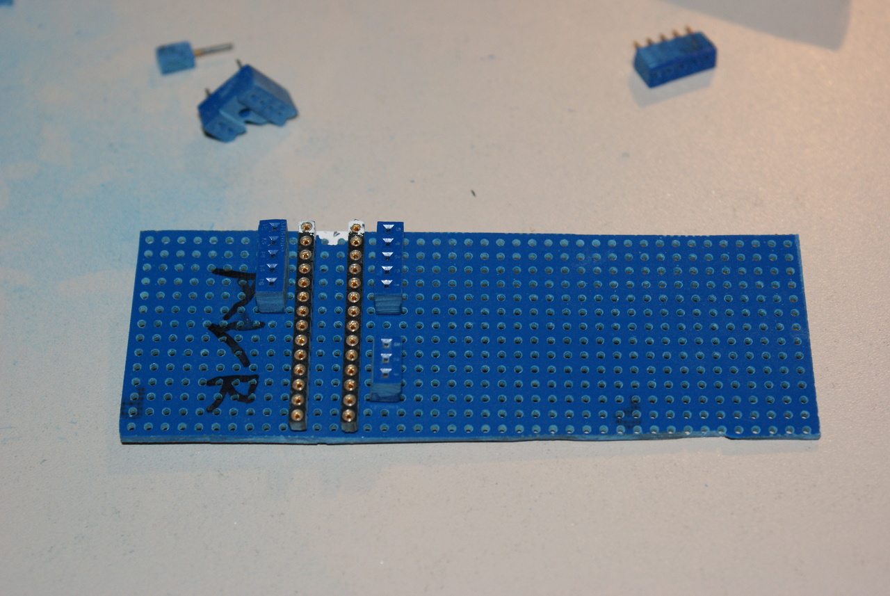
 The mainboard
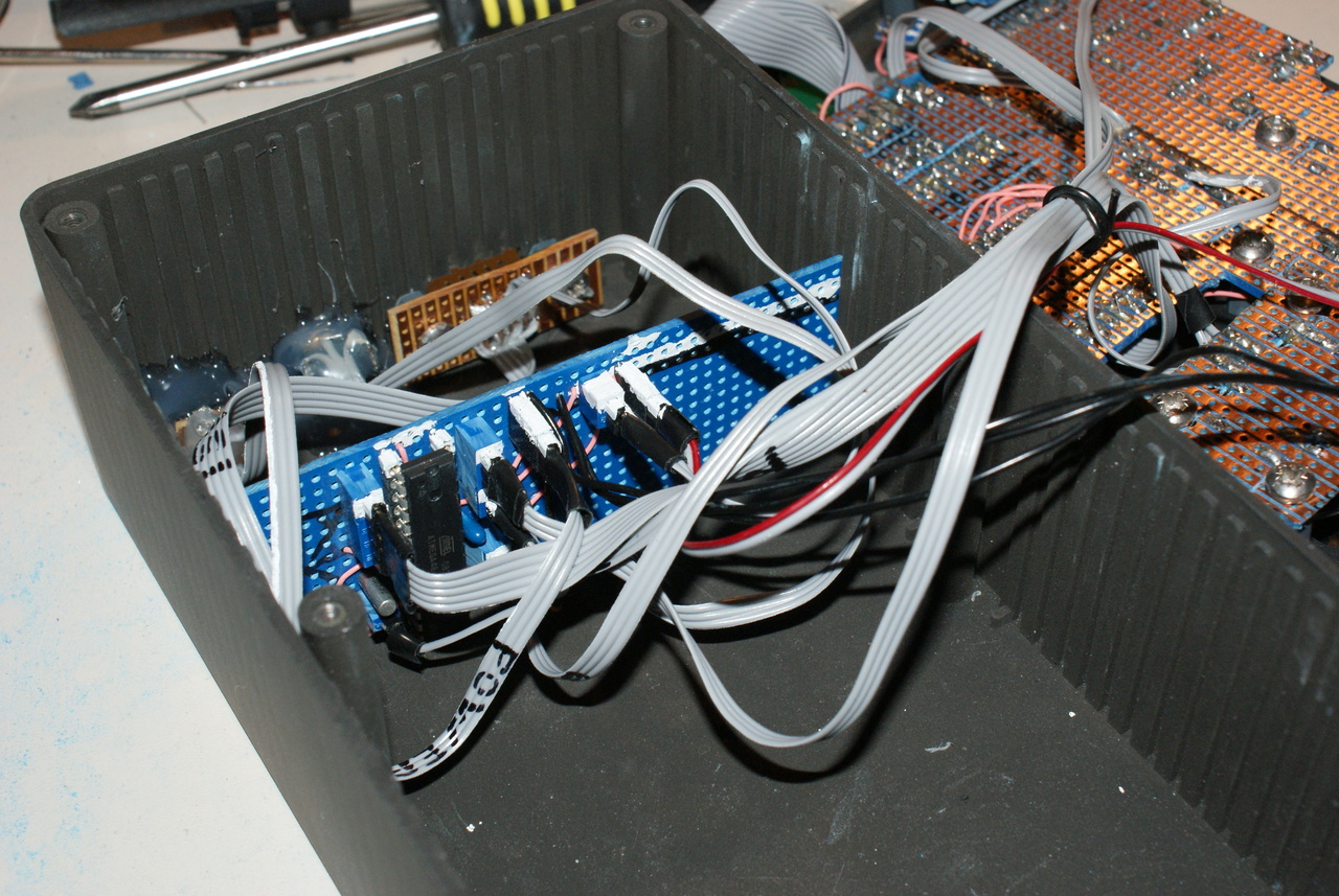
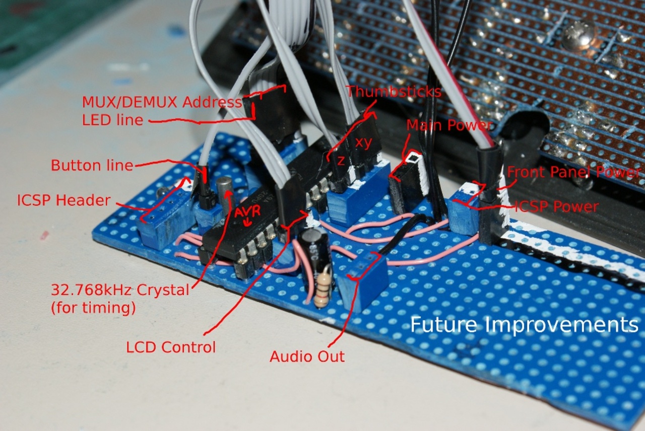
The plan was to run off an Atmega, so work began on the AVR board. I didn't have an IC socket big enough for the Atmega, so I used 2 rows of socket strip. That used up all of my strip, so started cannibalising IC sockets for the rest. I used tippex all over the place to mark 'pin-1's, I was going to have a lot of cables to keep track of.
The mainboard
The plan was to run off an Atmega, so work began on the AVR board. I didn't have an IC socket big enough for the Atmega, so I used 2 rows of socket strip. That used up all of my strip, so started cannibalising IC sockets for the rest. I used tippex all over the place to mark 'pin-1's, I was going to have a lot of cables to keep track of.
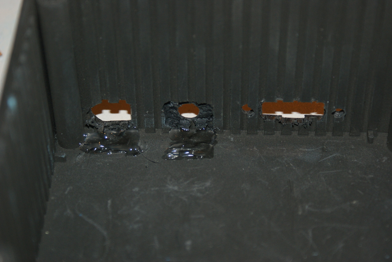
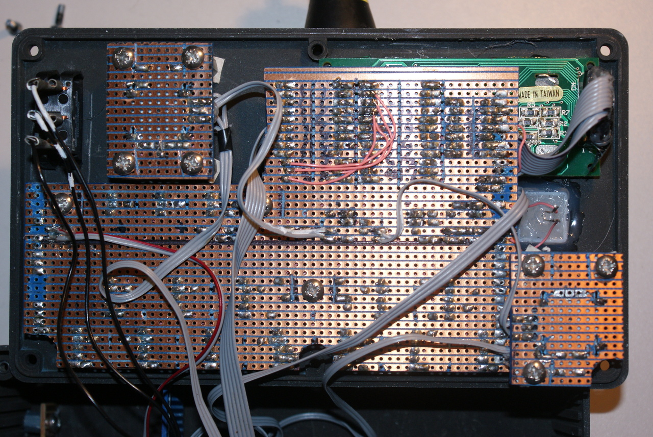
Once the mainboard was done, I drilled some holes in the side of the box for power, programming and audio output. I'm quite pleased with how neat I managed to get them.
Using a lot of ribbon cable, everything came together. All the cables are labelled with their function, pin-1s are marked and I just have to remember what goes in each socket, shown on the Openoffice Drawing above. There's still some space available on the mainboard, I think I might have to add a second processor dedicated to sound processing to really make this do all the things I want. The box is plenty big enough to add another couple of boards if necessary as well, possibly a powered output stage.
The mainboardOnce the mainboard was done, I drilled some holes in the side of the box for power, programming and audio output. I'm quite pleased with how neat I managed to get them.
Using a lot of ribbon cable, everything came together. All the cables are labelled with their function, pin-1s are marked and I just have to remember what goes in each socket, shown on the Openoffice Drawing above. There's still some space available on the mainboard, I think I might have to add a second processor dedicated to sound processing to really make this do all the things I want. The box is plenty big enough to add another couple of boards if necessary as well, possibly a powered output stage.
Software(top)
The software is very much a work-in-progress, it's written in C, using avr-libc. I won't upload the source until I've cleaned it up a little. The AVR is running off 8 MHz internal oscillator. Update this has been chagned to a 20 MHz external oscillator
The sound generation is done using DDS, the PWM mode of timer 1 and a low pass filter. In memory I have wavetables of sine, square, triangle and sawtooth waves. A value is read from the wavetable and set as the PWM duty. If you scan through all the elements of the wavetable you get one cycle of the wave at the output. Obviously the speed at which you do this determines your frequency output.
Wikipedia has this to say on DDS: http://en.wikipedia.org/wiki/Direct_digital_synthesis
I also had these two great projects as a reference:
http://www.scienceprog.com/avr-dds-signal-generator-v20/
http://www.myplace.nu/avr/minidds/index.htm
I update the phase accumulator on a timer interrupt, and the amount it is incremented by is set by a 'phase shift' variable. The LCD is controlled through a shift register, nothing that hasn't been done before. This means you can control it using just 3 pins from the micro. I wrote a few functions that will control the screen's operation and send it data. As well as a print_string() function and integer to string conversion: Very handy for debugging amongst other things!
The buttons and switches are run through the mux/demux.They share an address bus, which takes up 4 pins. The address is incremented each time the phase_accumulator interrupt happens, this gives plenty of refresh for flicker free lights. The button states and LED pins are read and written in there aswell. I use 2 16 bit integers to store the button and LED states (1 bit per button/LED.) These are global and so lighting an LED is as simple as setting its bit in the int. The interrupt routines take care of the rest.
I wrote some code to read the thumbsticks, which have an ADC per axis, x, y and z. You can request an analog value or a +1, 0, -1 for navigating menus etc. These are determined if the ADC value is above 205 (1) or below 50 (-1), or somewhere in the middle (0). A timer is used to count the beats, and the lights/buttons/sounds are updated on the interrupt of that. Glue it all together and you get what you see in the video!
Update: I have since added rudimentary support for multiple simulatneous notes. I'm having some trouble getting it working correctly
What's next?(top)
- I really want to add a lot more to this! For instance, I would like to have a LFO to allow me to modulate the amplitude/frequency of the output. I havent thought of a good way to do this in software without floating point arithmetic. Any help here would be greatly appreciated! Memory space isn't an issue - I'm using just over 4k at the moment, however I haven't got loooads of processing time in between interrupts.
- Obviously I need to add the possibility to change octave.
- Battery power!
- Built in speakers.
- Make the cycles 4 bars at a time instead of one bar.
- Loading/Saving of patterns.